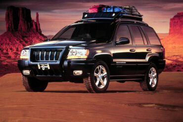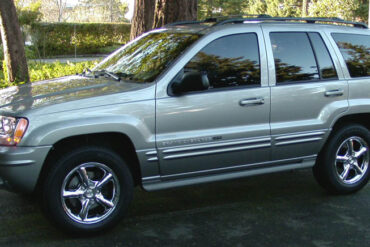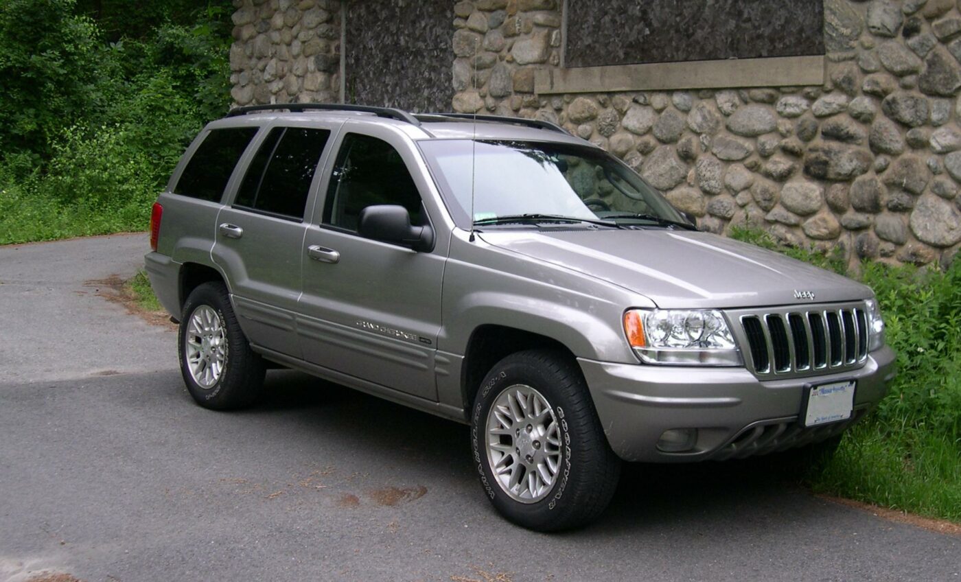
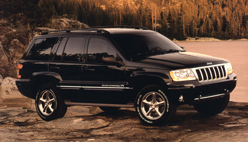
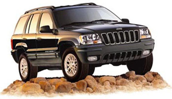
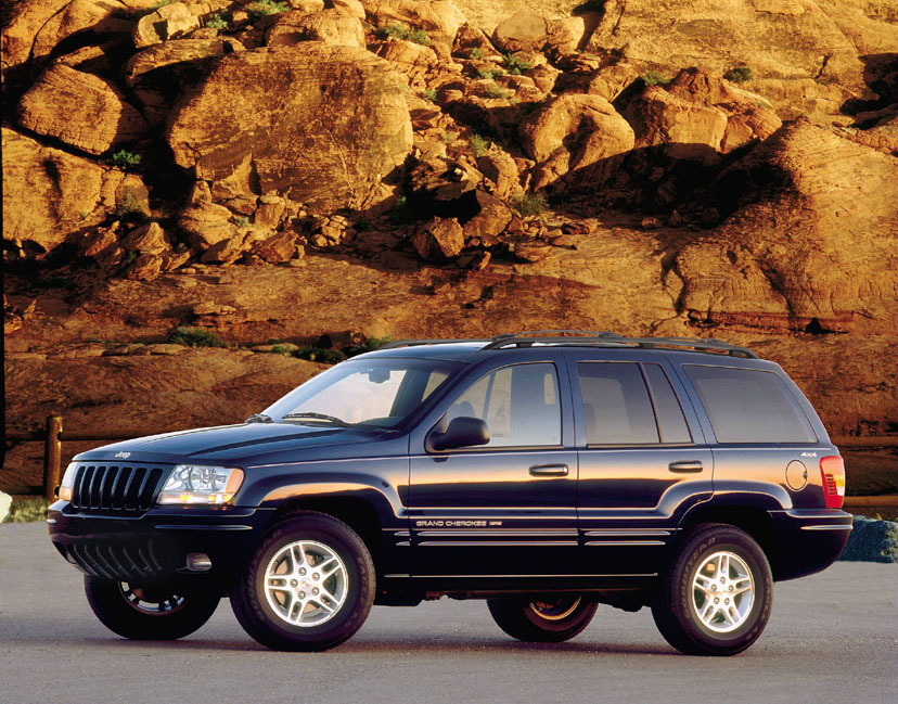
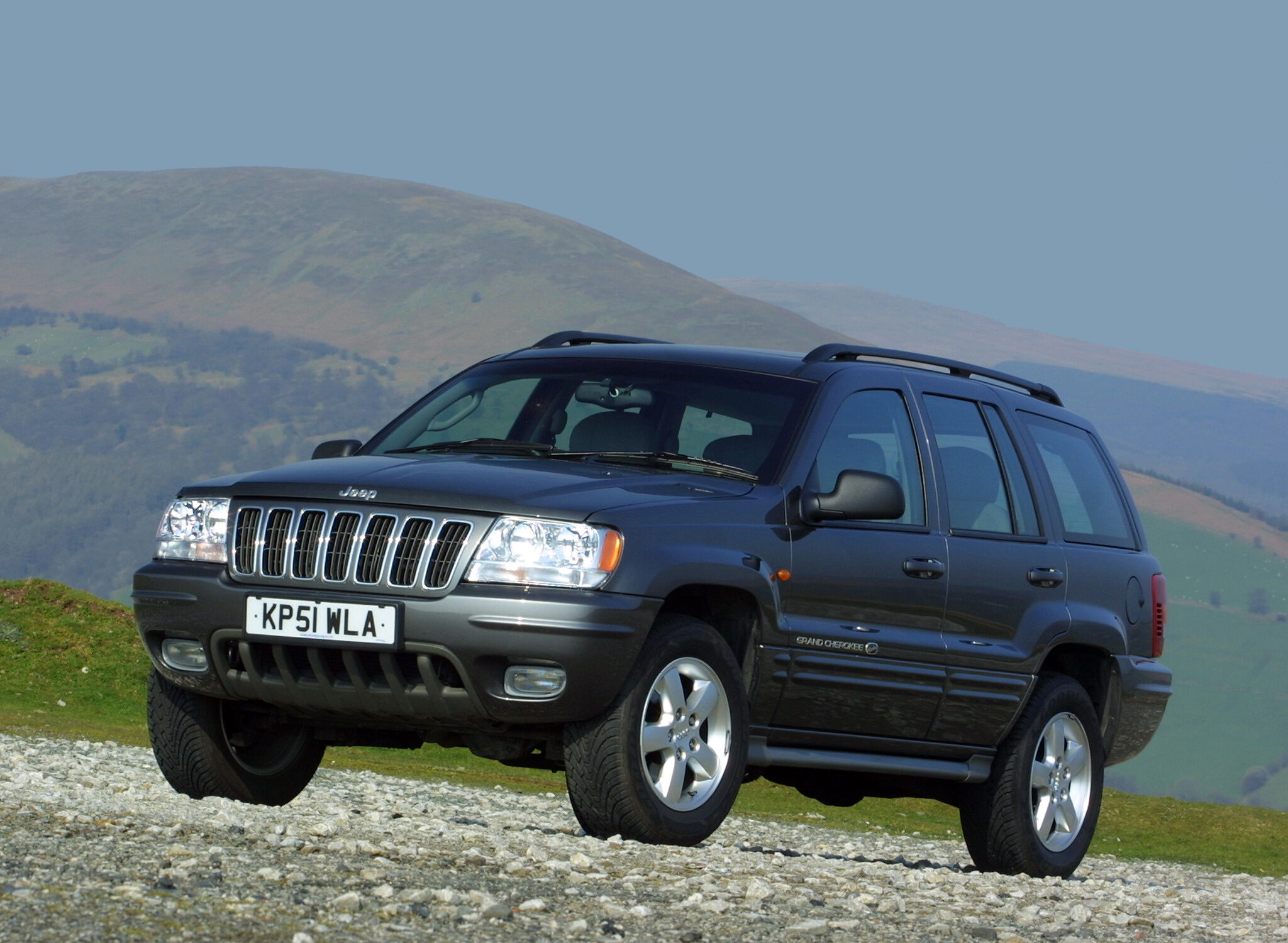
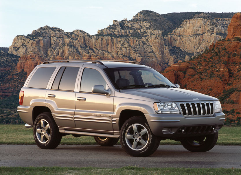
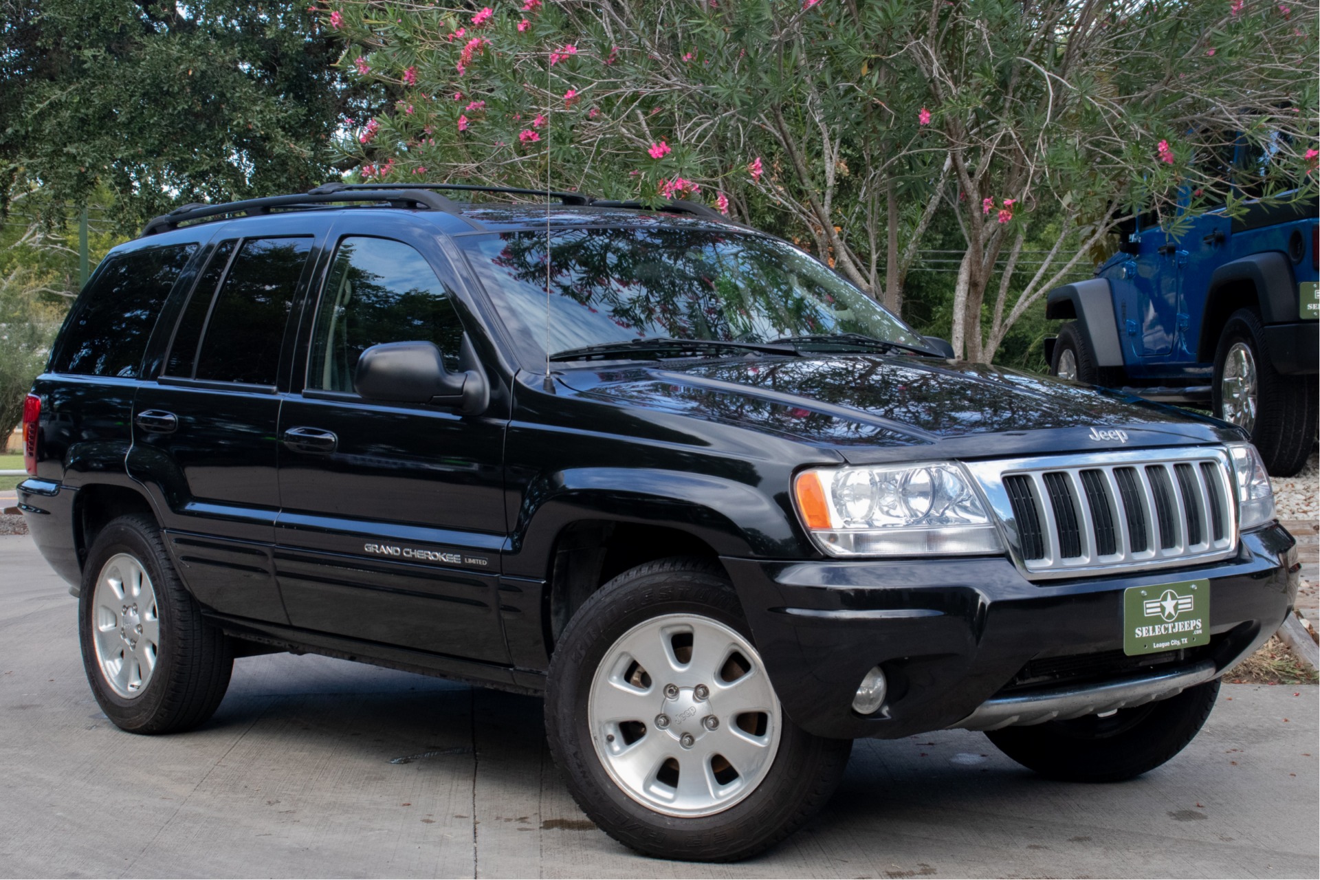
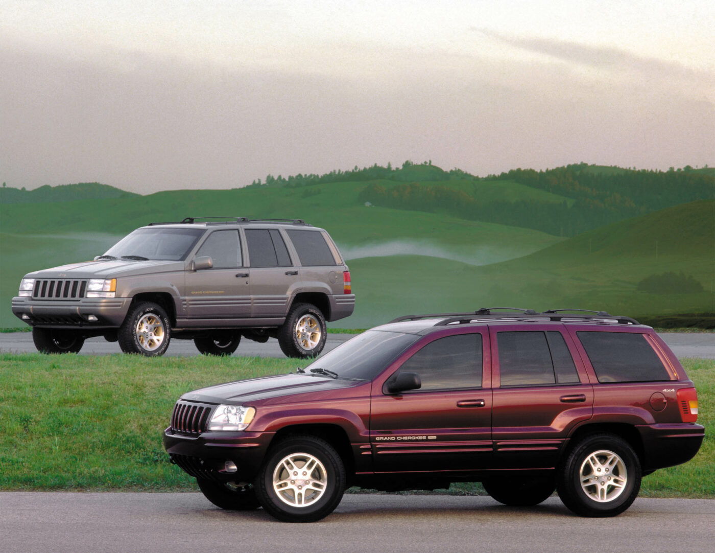
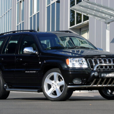
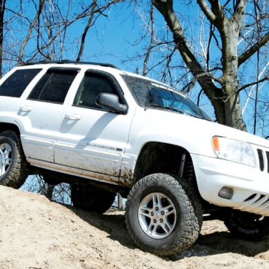
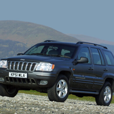
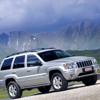
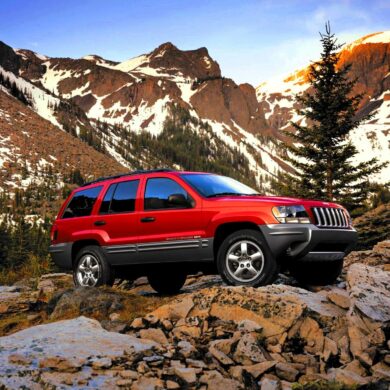
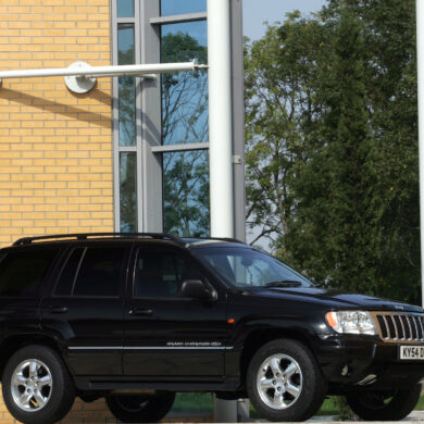
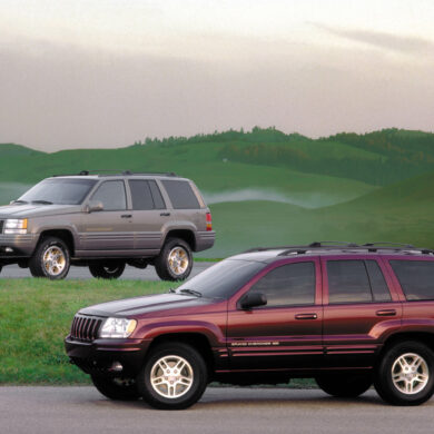
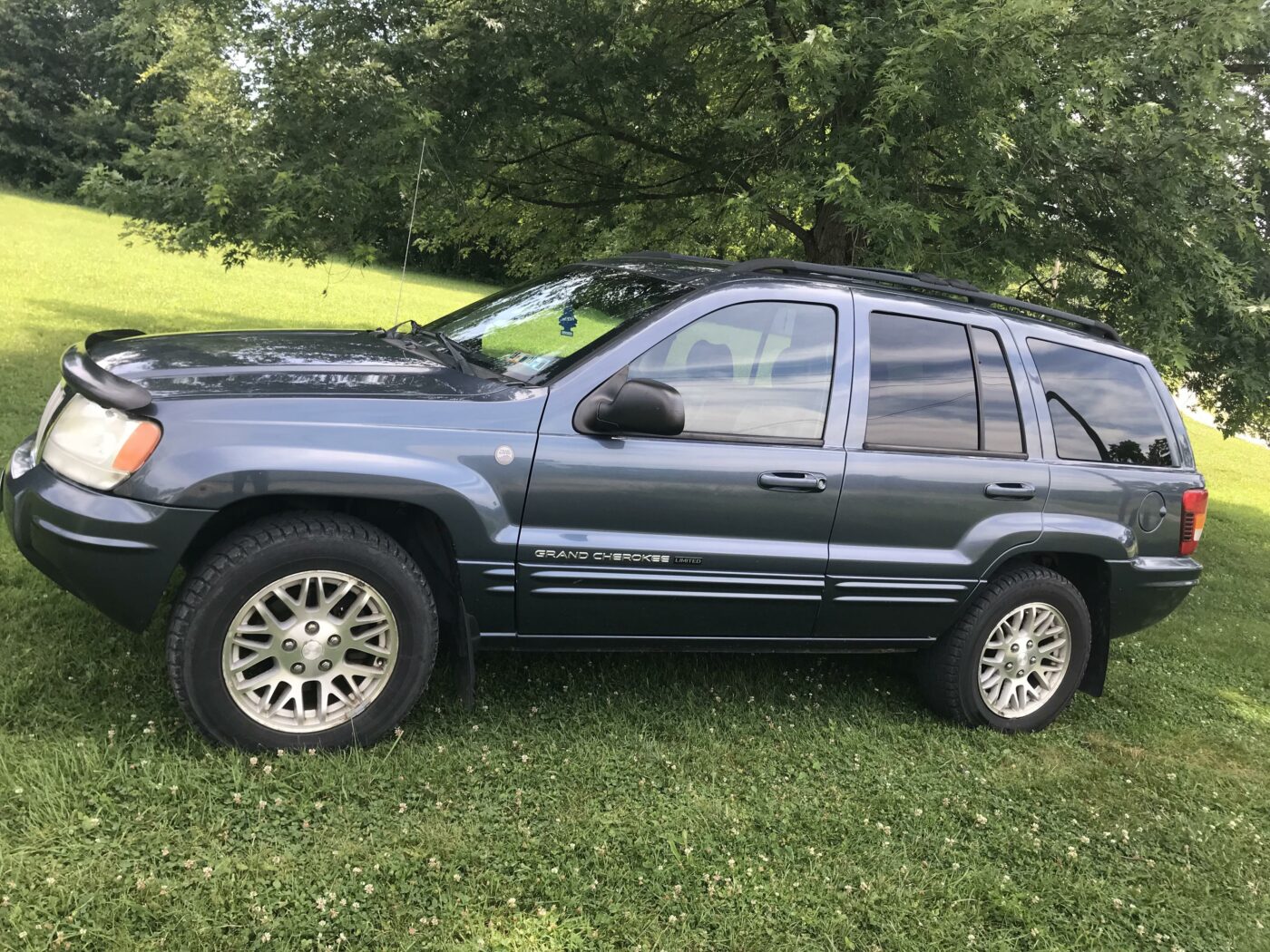
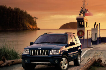
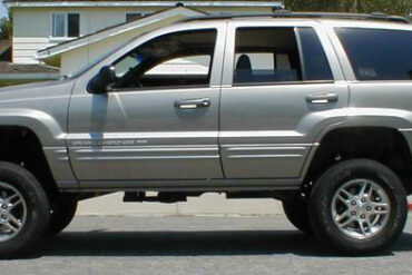
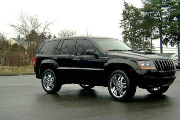
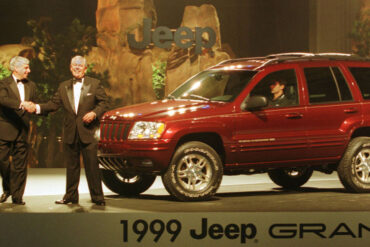
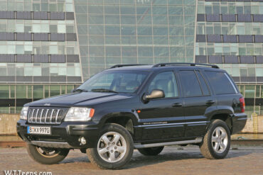
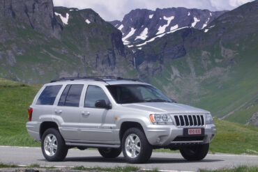
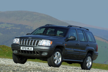
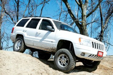
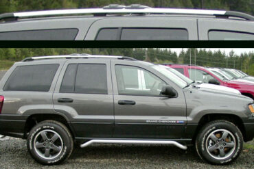
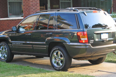
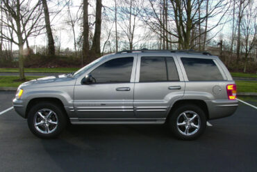
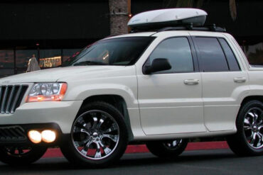
Second-Generation 1999 - 2004 Jeep "WJ" Grand Cherokee
Model-Year Guides / Technical Information / Pics & Videos
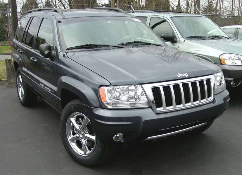
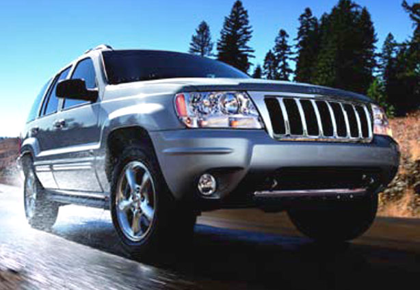
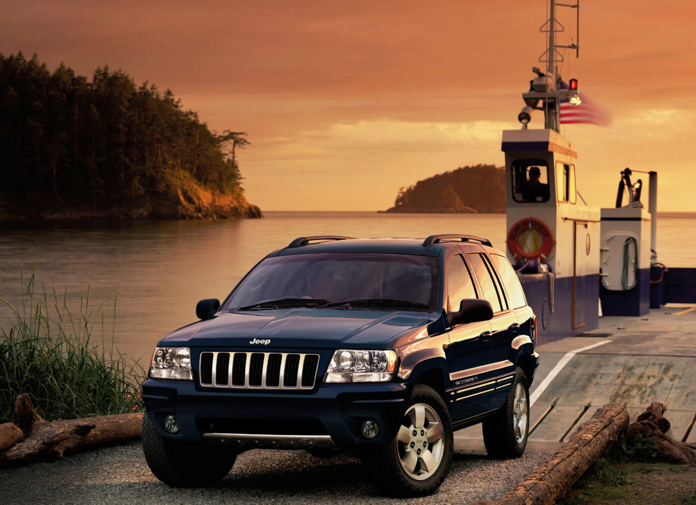
The second-generation Jeep Grand Cherokee was dubbed the "WJ" chassis ("WG" in for vehicles procued in Austria). Marketed as the "most capble SUV ever", the WJ generation Grand Cherokee is one of the most fondly remembered (and criticaly acclaimed) due to its impressive on/off-road performance and technology integration.
Jeep WJ Grand Cherokee Guide
Looking to go deep on the Jeep WJ Grand Cherokee? No problem - our comprehensive Jeep WJ guide covers everything that current and prospective owners need to know about the second-generation Grand Cherokee.

A Brief Jeep WJ Grand Cherokee History Lesson
Even with the success of the ZJ Cherokee, Jeep decided to not sit on its laurels. The WJ Grand Cherokee was redesigned to the point of only carrying 127 pieces with its predecessor - and most were fasteners. The new WJ benefited from new tech like GPS Navigation and Bluetooth, but also carried larger rims, upscale interior, and more powerful engines.
New Technology Features
By the late-90s, technology was finally making its way to mainstream vehicles. Multi-disc CD players, in-car cellular phones, and dual-zone climate control were no longer relegated to the realm of the oppulent.
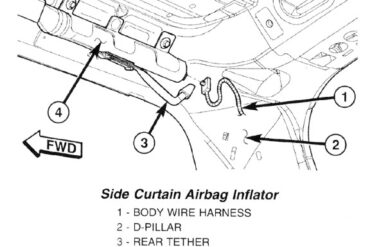
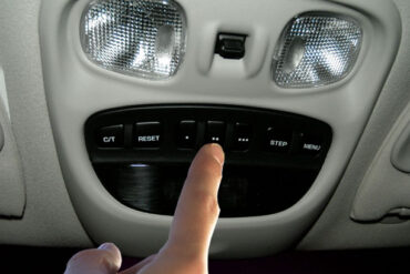
The WJ Grand Cherokee introduced class-first features, such as HomeLink, dual-zone climate control, driver memory systems, power-adjustable foot pedals, SRS side-curtain airbags, Uconnect Bluetooth connectivity, and Sirius satellite radio (among many others).
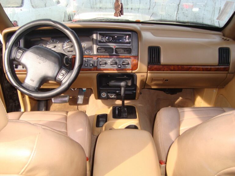
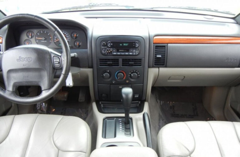
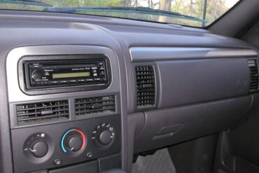
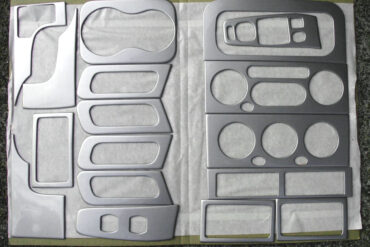
A Friendlier, More User-Centric Interior
The push upmarket included a revitalized interior, which featured a user-friendly layout that priotized accessibility of important functions/switches. It featured comfortable multi-adjustable leather seats up front and increased rear-passenger room (with larger rear-doors for easier accessibility as well).
Luxury features, such as heated seats, premium Infinity audio system, and Sirius Satellite Radio helped transform the interior of the WJ into a quiet and entertaining place.
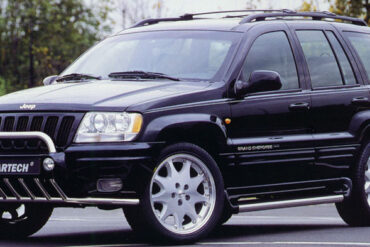
New Engines, Transmissions, & "Quadra-Drive"
A new automatic four wheel drive system called Quadra-Drive was introduced in the WJ. This is where the drive system can send needed torque to the front and rear wheels as necessary.
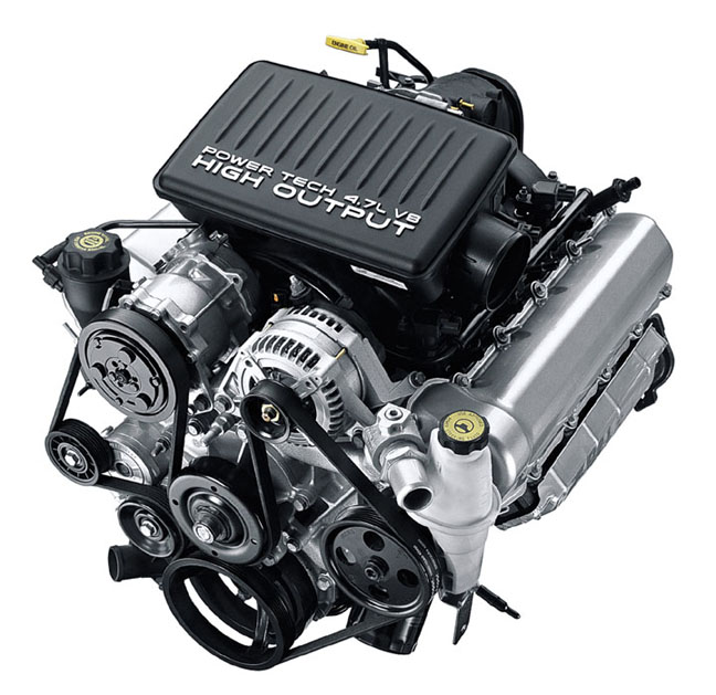
Old-school pushrod V8's were replaced by a newly-developed 4.7L PowerTech V8 that was lighter, more efficient, and more powerful (235 hp or a 265 hp high-output V8). The 4.0L AMC I6 was also revised, adding an additional 10 more horsepower (totalling 195 hp).
The "4-Speed" 45RFE and "5-Speed" 545RFE transmissions used three planetary gear sets. These were theoretically capable of six-gears and could have been the first 6-speed transmission but it was programmed for five.
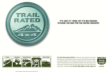
A Stiffer Body for More Capable On & Off-Road Manners
The Grand Cherokee utilizes Jeep's UniFrame framework, which is a method of construction that attempts to combine the practical benefits of body-on-frame consruction (durability, ease of build/repair) with the efficiencies and strength of unibody construction.
Extra attention was paid to driving mannerisms, with investments in the chassis made to reduce noise and vibration while driving. The result was a chassis that was compliant and comfortable on-road, while maintaing competence in all but the most hardcore of off-road trails.
Grand Cherokee WJ Model-Year Guides
Meticulously researched and curated, our comprehensive Jeep WJ model-year guides illustrate changes from year to year, specifications, available options, and more.

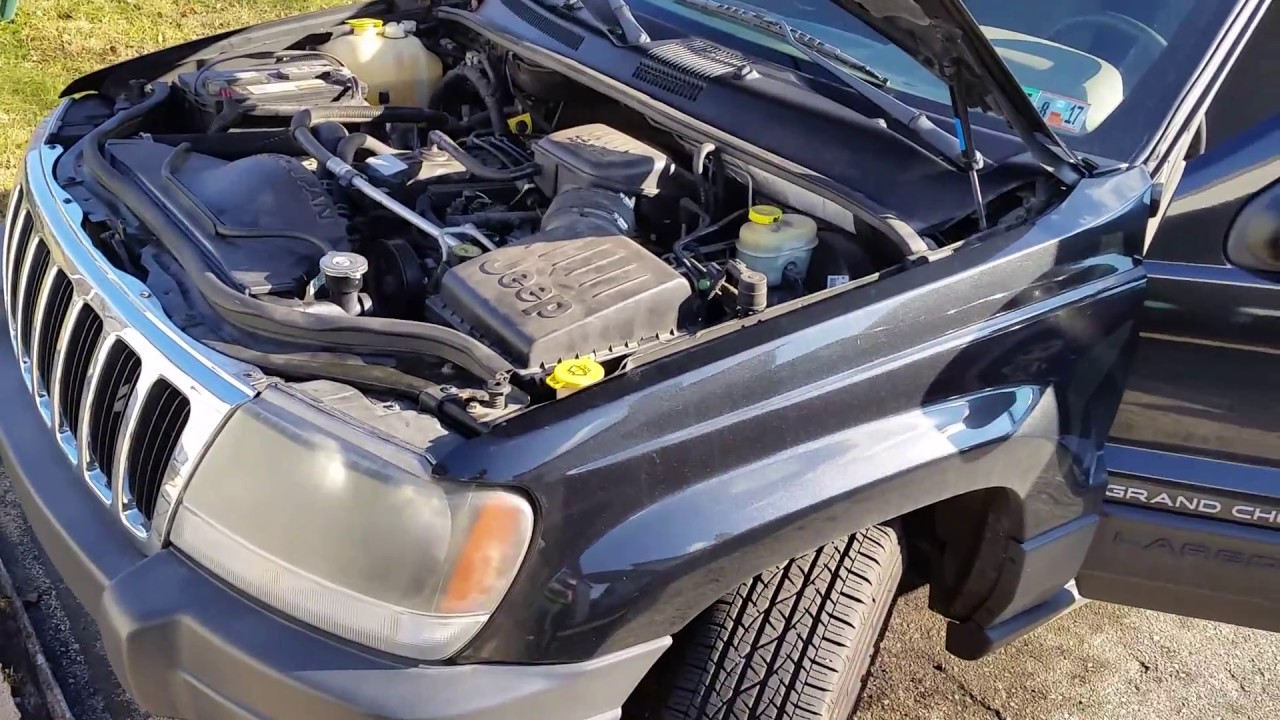
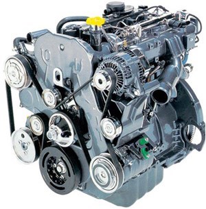
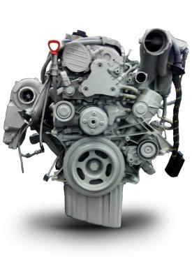
Jeep WJ Engines
The computers in cars were getting more capable, and advances in manufacturing and materials meant that the WJ generation enjoyed powerful engine options in six-cylinder, eight-cylinder, and available five-cyldinder diesels (Europe only). As of 1999, every Jeep Grand Cherokee in North America was sporting at least 195 horsepower.
4.0L PowerTech Inline-6
Available for the 1999 - 2004 model years.
A revised intake manifold meant that Jeep's trusty 4L I6 was now making a respectable 195 horsepower and 230 lb-ft of torque. The PowerTech I6 was a fairly reliable engine, though some manufactured in 2000 were prone to cracked cylinder heads between the #3 and #4 cylinders.
Note: despite the common name ("PowerTech"), the PowerTech I6 is not related to the PowerTech V8.
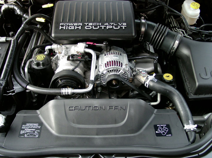
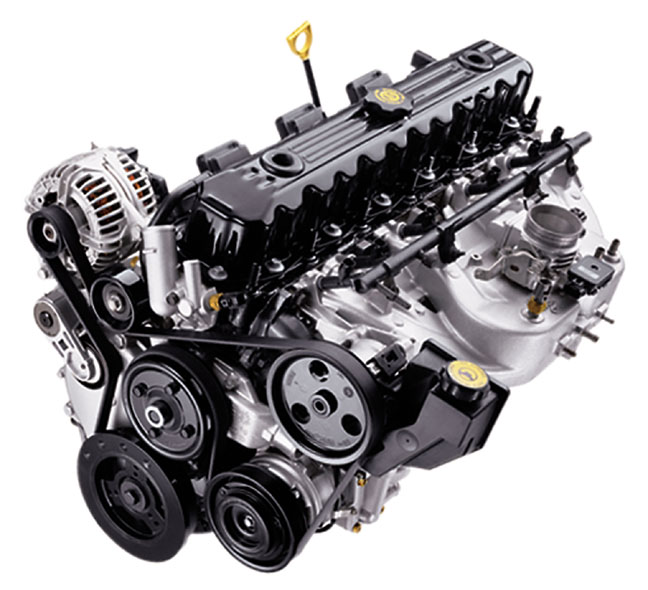
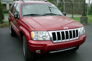
4.7L PowerTech V8
Available for the 1999 - 2004 model years.
With 235 horsepower and an abundant 295 lb-ft of torque, the PowerTech V8 proved to be a reliable power plant.
In addition to the Jeep WJ, the 4.7L PowerTech V8 was found in the Chrysler Aspen, Dodge Dakota, Dodge Durango, Dodge Ram 1500, Jeep Commander, and Mitsubishi Raider
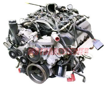
4.7L High-Output PowerTech V8
Available for the 2002 - 2004 model years.
The 4.7 High Output V8 first appeared in 2002. Output was 265 horsepower and 330 lb-ft of torque - some 13% increase. This V8 would run until it was discontinued in 2008. In addition to the Grand Cherokee, the 4.7 HO was found in the Dodge Dakota and Dodge Ram 1500.
3.1L Diesel Inline-5
Available for the 1999 - 2001 model years.
Only available in Europe, South Africa, and Australia, the 3.1L diesel five-cylinder engine made 138 horsepower and 283 lb-ft of torque. Notably, the torque peaked at just 1,800 rpm, making the diesel an excellent city and off-road vehicle.
2.7L Diesel Inline-5
Available for the 2002 - 2004 model years.
Only available in Europe, South Africa, and Australia, and developed by Mercedes-Benz, the OM612 diesel I5 produced 161 horsepower and 295 lb-ft of torque.
Join Our Jeep & Off-Road Enthusiast Newsletter
For every mountain there's a Jeep to climb it. Get the latest on what's happening with Jeep in our exclusive no-spam, no-marketing newsletter. Every email handwritten by a real person based somewhere in North America. We know - the concept astounds you.
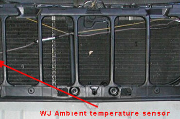
Jeep WJ Photos, Videos, & Other Media
Sourced from fellow Jeep enthusiasts around the web.
Jeep WJ Wallpapers
Jeep WJ Videos
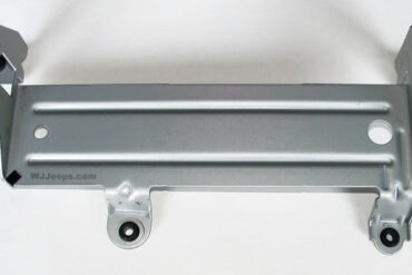
Jeep WJ Technical Specifications
From lighting to suspension, physical dimensions to in car electronics, we have meticulously curated a incredible amount of WJ Grand Cherokee resources, technical specifications, data sheets, and more.


Even More Jeep WJ
Our latest Jeep WJ content is posted here. Looking for something else? See more Jeep Grand Cherokee content.